Inhaltsverzeichnis
PWM in C mit dem myMM32 Board Light
//---------------------------------------------------------------------------
// Title     : simple PWM Solution, ARM C application in SiSy
//---------------------------------------------------------------------------
// Function  : ...
// Wiring    : ...
//---------------------------------------------------------------------------
// Hardware  : ...
// Clock     : ... MHz
// Language  : ARM C
// Date      : ...
// Version   : ...
// Author    : ...
//---------------------------------------------------------------------------
#include <stddef.h>
#include <stdlib.h>
#include "hardware.h"

#define F_PWM 5000  // 5kHz PWM frequency
volatile uint16_t timerPeriod = 0;
volatile uint16_t pwmLevel = 0; // 0 to timerPeriod

void initApplication() {
    // 1. Initialize SysTick
    SysTick_Config(SystemCoreClock/100);

    // 2. Enable GPIOB clock
    RCC_AHBPeriphClockCmd(RCC_AHBPeriph_GPIOB, ENABLE);

    // 3. Configure PB0 as TIM3_CH2 alternate function
    GPIO_InitTypeDef GPIO_InitStruct;
    GPIO_InitStruct.GPIO_Pin = GPIO_Pin_0;
    GPIO_InitStruct.GPIO_Mode = GPIO_Mode_AF_PP;
    GPIO_InitStruct.GPIO_Speed = GPIO_Speed_50MHz;
    GPIO_Init(GPIOB, &GPIO_InitStruct);
    GPIO_PinAFConfig(GPIOB, GPIO_PinSource0, GPIO_AF_1); // TIM3_CH2

    // 4. Calculate timer period
    timerPeriod = (SystemCoreClock / (F_PWM * 5)) - 1; // Prescaler of 5

    // 5. Enable TIM3 clock
    RCC_APB1PeriphClockCmd(RCC_APB1Periph_TIM3, ENABLE);

    // 6. Configure TIM3 base
    TIM_TimeBaseInitTypeDef TIM_TimeBaseStruct;
    TIM_TimeBaseStruct.TIM_Prescaler = 5 - 1;  // 5x prescaler
    TIM_TimeBaseStruct.TIM_CounterMode = TIM_CounterMode_Up;
    TIM_TimeBaseStruct.TIM_Period = timerPeriod;
    TIM_TimeBaseStruct.TIM_ClockDivision = TIM_CKD_DIV1;
    TIM_TimeBaseStruct.TIM_RepetitionCounter = 0;
    TIM_TimeBaseInit(TIM3, &TIM_TimeBaseStruct);

    // 7. Initial 50% duty cycle
    pwmLevel = timerPeriod / 2;

    // 8. Configure PWM channel 2
    TIM_OCInitTypeDef TIM_OCStruct;
    TIM_OCStruct.TIM_OCMode = TIM_OCMode_PWM2;
    TIM_OCStruct.TIM_OutputState = TIM_OutputState_Enable;
    TIM_OCStruct.TIM_Pulse = pwmLevel;
    TIM_OCStruct.TIM_OCPolarity = TIM_OCPolarity_High;
    TIM_OC2Init(TIM3, &TIM_OCStruct);

    // 9. Enable TIM3
    TIM_Cmd(TIM3, ENABLE);
    TIM_CtrlPWMOutputs(TIM3, ENABLE);
}

int main(void) {
    SystemInit();
    initApplication();
    bool dimUp = true;

    while(1) {
        if (dimUp) {
            if(pwmLevel < timerPeriod/2) {
                pwmLevel++;
            } else {
                dimUp = false;
            }
        } else {
            if(pwmLevel > 0) {
                pwmLevel--;
            } else {
                dimUp = true;
            }
        }

        TIM_SetCompare2(TIM3, pwmLevel);
        waitMs(1);
    }

    return 0;
}

void SysTick_Handler(void) {
    // SysTick interrupt handler
}
//------------------------------------------------------------------------
Test
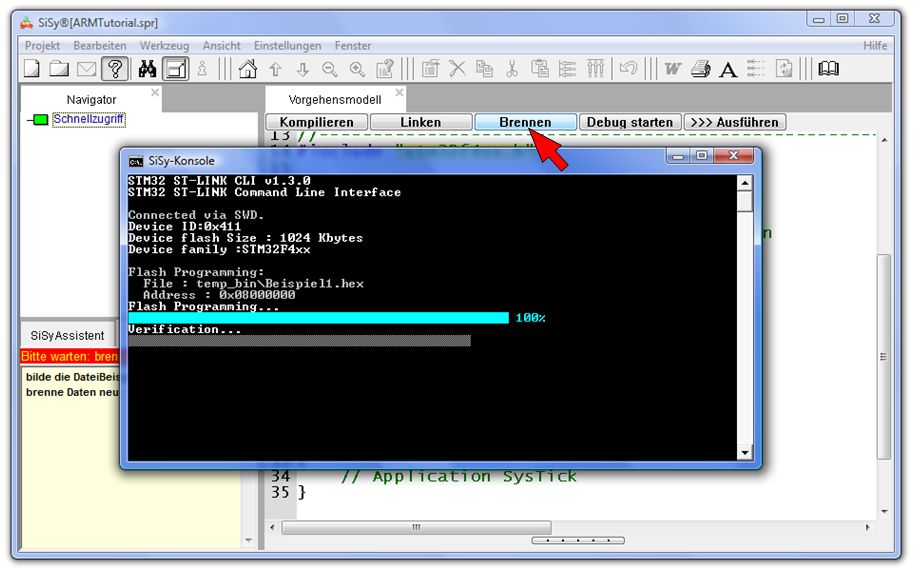
Nutzen sie die Schaltflächen Kompilieren, Linken und Brennen. Stellen Sie die nötigen Verbindungen auf dem Board mit den dafür vorgesehenen Patchkabeln her. Testen Sie die Anwendung.